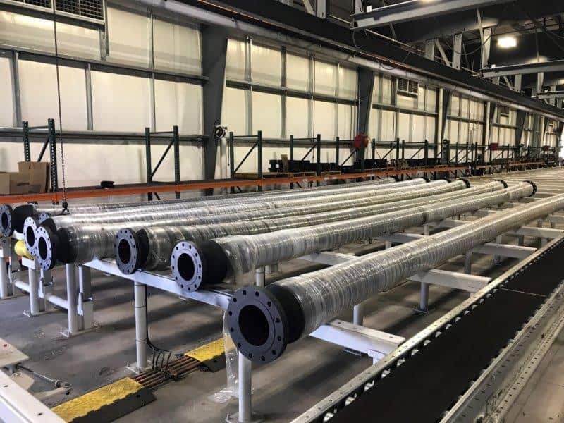
All offshore hoses are manufactured to meet or exceed the requirements of the OCIMF Guide to Purchasing, Manufacturing and Testing of the Loading and Discharge Hoses for Offshore Moorings, 4th Edition 1991.
Daytona Type Mainline Submarine Hose Series 297
Standard-based submarine hose construction.
Electronically continuous or discontinuous (TBA). 300 PSI MAX WP, 1500 PSI MIN BP. Double high-grade Nitrile tube suitable for use with up to 60% aromatic content fuels, multiple plies of high tensile polyester tire cord reinforcement, high grade spring steel helix wire, double cover separated by an orange color ply as a wear indicator.
Cover is resistant to wear, aging, stress, abrasion, weathering, sunlight, oil and saltwater penetration. Built-in, standard weight, seamless, carbon steel nipples with 150 lb. ANSI B 16.5 fixed weld neck raised-face flange.
All welded parts are X-rayed and/or mag particle tested. Manufactured with OCIMF certification. Hydro-tested without kerosene testing. Slat packed and with nylon slings for lifting.
All hoses are rated for a maximum working pressure of 300psi with a minimum burst pressure of 1500psi. Underwater weight and negative buoyancy are only guaranteed when full of product or saltwater (per OCIMF 1991).
- I.D. (inch)
- 4″
- 6″
- 8″
- 10″
- 12″
- O.D. (mm)
- 6.93
- 8.78
- 11.09
- 13.71
- 15.88
- Weight (lbs/30ft)
- 315
- 566
- 851
- 1252
- 1580
- End Weights (lbs)
- 76
- 138
- 194
- 274
- 392
Daytona Type Tanker Rail Hose Series 298
Basic hose is constructed as the MAINLINE, but above the Helix Wire additional tapering reinforcement is added extending from each end to a maximum length of 10ft into the body. This provides extra stiffness over the end sections to allow for the hose taking up its normal operational position of a 90 degree bend from the tanker manifold, clear of and over the ship’s rail.
Additional standard features include lifting and snubbing lugs, 2 at the TANKER end and 1 at the TAIL end, unless otherwise required by order.
Electrical properties must be stated at inquiry/order stage.
Branding as per OCIMF 1991 indicates the tanker rail end (as well as the standard double lug).
All hoses are rated for a maximum working pressure of 300psi with a minimum burst pressure of 1500psi. Underwater weight and negative buoyancy are only guaranteed when full of product or saltwater (per OCIMF 1991).
- I.D. (inch)
- 4″
- 6″
- 8″
- 10″
- 12″
- O.D. (mm)
- 6.93
- 9.26
- 11.57
- 13.98
- 16.24
- Weight (lbs/ft)
- 13.40
- 21.82
- 32.08
- 44.04
- 56.20
- Weight (lbs/30ft)
- 402
- 654.6
- 962.4
- 1321.20
- 1686
- End Weights (lbs)
- 78
- 141
- 198
- 279
- 398
Daytona Type PLEM Hose Series 299
Electrically continuous or discontinuous (TBA). 300 PSI MAX. 1500 PSI MIN BP. Double high-grade Nitrile tube (suitable for use with up to 60% aromatic content fuels), multiple plies of high-tensile polyester tire cord reinforcement, high-grade spring steel helix wire, double cover separated by an orange color ply as a wear indicator.
1/3 of hose from one end with extra reinforcement for the PLEM connection.
All hoses are rated for a maximum working pressure of 300psi with a minimum burst pressure of 1500psi. Underwater weight and negative buoyancy are only guaranteed when full of product or seawater (per OCIMF 1991).
- I.D. (inch)
- 4″
- 6″
- 8″
- 10″
- 12″
- O.D. (mm)
- 6.69
- 9.03
- 11.67
- 13.98
- 16.24
- Weight (lbs/ft)
- 11.96
- 19.91
- 33.34
- 43.80
- 56.20
- Weight (lbs/30ft)
- 359
- 597
- 1000
- 1314
- 1686
- End Weights (lbs)
- 76
- 138
- 194
- 274
- 392
Maintenance and Operating Instructions
Regular maintenance of your hose and ancillary equipment will undoubtedly extend the life of your equipment and reduce the risk of pollution. Following these general guidelines will assist you in this goal.
Considerations for installation
• Establish uniform procedures which will avoid rough handling and over-bending during the installation process.
• Ensure that contingency plans for inclement weather are in place when planning installation.
Considerations for operation
Operational procedures will invariably differ from site to site due to weather conditions and tanker frequency. Attention to the following general guidelines will assist in smooth operations:
• Hose handling vessels should be purpose-built, powerful and highly maneuverable (preferably twin screw). They should have a flat open stern section, equipped with winches compatible with the weights of hoses in use, and should be in radio contact with the mooring master aboard the berthing tanker. To avoid damage to hoses during “alongside” maneuvers, boats should be fitted with propeller guards.
• Initially, hoses should be checked daily to become familiar with how they behave during tide changes. Submarine hoses should be checked before and after each tanker loading, as well as after storms.
• Hose handling equipment such as tail and lifting gear, should be properly modified if necessary to suit the preferences and equipment of handling crews.
• Extreme care should be taken to ensure that the rail hose is not overbent. Proper use of snubbing chains and wires is essential.
• Operation crews need to assess the necessary spare hose requirements and develop a maintenance schedule based upon this assessment.
Maintenance
Maintenance of submarine hoses is limited to visual external inspections. Following the general guidelines below will ensure the maximum results from your inspections:
• Inspect hoses at zero internal pressure and at full working pressure. Maintenance divers should inspect hose configuration to ensure that no adjustments are necessary
• Check the cover of each hose for damage due to chafing. Check each hose carcass for kinks, particularly at connections to rigid areas of the system (manifold connections and buoyancy tanks.) Inspect bolts for tightness. All flanges and hoses should be checked for leaks under pressure.
• System-wide valve arrangements should be such that if a hose failure occurs in one submarine hose in a string, loading can be achieved through the remaining hose string while the failure is being cured.
• Sufficient spare submarine hose should be kept on hand for each applicable size.
Handling
Great care should be taken when handling hoses at the terminal. They should only be lifted on a spreader bar which provides 3-point support. They should never be lifted from a centrally-placed sling with flanges hanging down or from both flanges with the center hanging unsupported. Do not lift hoses with conventional fork lift trucks.


